
With all of the basics now covered, I thought it might be interesting to talk about the operation of the clock, and hopefully leave you with a good insight in to how it will function internally in order to produce the ever familiar output.
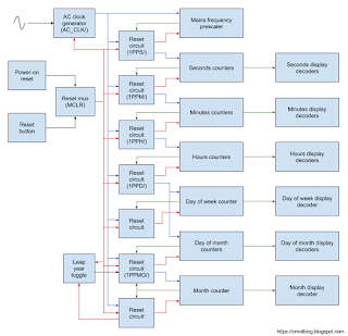
Here's a block diagram of all of the major parts to get started with:
And throughout the rest of this post I will (try to) explain the relationship of all of the items so that you understand what makes the clock tick (pun intended). There's a lot of repetition, so once you understand one little bit of it, you'll probably understand almost all of it.
But first, some terminology needs covering.
Things enclosed in parentheses indicate output signal names, for example, (AC_CLK/) indicates that AC_CLK/ is the signal output from that piece of the circuit.
Blue lines indicate clock signals, and there are numerous clock signals generated within the various modules of my clock which are used to advance successive counters, from seconds to minutes to hours to days and so on.
Green lines indicate counter outputs, and are usually multi-bit binary values. These outputs feed in to decoders that drive displays, and also in to reset circuitry that resets the counters and generates the various clock signals.
Red lines indicate reset signals which are used to either reset the entire clock (as in the case of MCLR), or only small portions of it, such as a single counter.
Black lines are generic signals.
Otherwise all of the boxes are labelled to indicate their purpose, and the lines are all capped off with an arrow head at one end indicating the direction that the signal is used.
This prescaler is tied to a reset circuit. The reset circuit can be configured to reset the prescaler at any value up to 63 because it's a 6 bit counter, so the clock can be used anywhere around the world, but in my case it will be configured to reset at 50 count because of where I'm located.
Upon the prescaler reaching 50 count, the reset circuit sets an SR latch sending its Q output high and complementary output (Q/ or "not Q") low. Q feeds in to the reset input of all of the D type flip flops that are part of the prescaler counter resetting them to 0, and Q/ creates a clock pulse to the seconds counter which is referred to as 1PPS_CLK/ (1 pulse per second).
On the rising edge of the next AC_CLK/ pulse, the SR latch will be reset causing its Q output to go low and releasing the reset on the counter, and Q/ output goes high. In this state the counter is at 0 count, and the next falling edge of AC_CLK/ will cause the counter to increment by 1.
Since I lack the requisite skills to make a fancy video, or maybe even an animation describing this, I'll try to illustrate it by way of another timing diagram. So here goes:

The very top signal of the timing diagram is AC_CLK/, oscillating back and forth between high and low states. The two signals below indicate the state of the SR latch outputs that form part of the reset circuit for the prescaler. Q feeds the reset of the counter, and Q/ forms the 1PPS_CLK/ signal to the seconds counter. PS 1 through PS 32 indicate the state of the Q outputs of the individual stages that make up the counter. A NOR gate connected to the complementary (i.e. Q/) outputs of PS 2, 16 and 32 acts as an AND gate to create a brief pulse in to the SR latch which triggers the reset when the count reaches 50.
So at the very left hand side of the timing diagram you see that PS 1, 2, 4 and 8 are low (0), and PS 16 and 32 are high (1), equalling a value of 48. At the falling edge of the first clock pulse you see that PS 1 transitions to a high state, so now the counter is representing a value of 49 (1+16+32). Then at the falling edge of the second clock pulse, PS 1 transitions to a low state, and that causes PS 2 to transition to a high state such that the counter now represents a value of 50.
As I have tried to represent in the diagram, it doesn't stay in this state for very long (on the order of nanoseconds really). At the point that PS 2, 16 and 32 are high, the NOR gate connected to the complement of those outputs goes high at its output (all low inputs = high output), and this causes the SR latch to invert its state. The Q output of the SR latch causes the counter to reset to 0, so you see after a short blip of PS 2 being high, it along with PS 16 and 32 all transition to a low state, and the counter now has a value of 0 with PS 1-32 all being low. And when Q/ of the SR latch transitioned to a low state, the falling edge of that signal would have caused the seconds counter to increment.
At the rising edge of the third pulse of AC_CLK/ you see that the SR latch inverts state again as it gets reset, and then at the falling edge of the third pulse you see that PS 1 goes high and we are back to a value of 1 again. It will continue incrementing until it reaches 50 count again, at which point it resets, generates another 1PPS_CLK/ pulse, and the seconds counter increments again. Lather, rinse, repeat until the end of time (or the power goes out).
Hopefully that gives you an idea of how the different clock pulses will be generated - they all operate in pretty much exactly the same way. Now I'll try and explain in a little more detail how everything ties together.

Here's a block diagram of all of the major parts to get started with:

And throughout the rest of this post I will (try to) explain the relationship of all of the items so that you understand what makes the clock tick (pun intended). There's a lot of repetition, so once you understand one little bit of it, you'll probably understand almost all of it.
But first, some terminology needs covering.
Things enclosed in parentheses indicate output signal names, for example, (AC_CLK/) indicates that AC_CLK/ is the signal output from that piece of the circuit.
Blue lines indicate clock signals, and there are numerous clock signals generated within the various modules of my clock which are used to advance successive counters, from seconds to minutes to hours to days and so on.
Green lines indicate counter outputs, and are usually multi-bit binary values. These outputs feed in to decoders that drive displays, and also in to reset circuitry that resets the counters and generates the various clock signals.
Red lines indicate reset signals which are used to either reset the entire clock (as in the case of MCLR), or only small portions of it, such as a single counter.
Black lines are generic signals.
Otherwise all of the boxes are labelled to indicate their purpose, and the lines are all capped off with an arrow head at one end indicating the direction that the signal is used.
Mains frequency prescaler
A simple circuit is used to produce a clock pulse of sorts from one half of the AC sinewave. This clock pulse is referred to as the AC_CLK/ signal because it pulses at the same frequency as the AC supply. It feeds the mains frequency prescaler, which increments on each falling edge of the AC_CLK/ signal. The forward slash indicates that it is an inverted signal, because AC_CLK/ is high when the AC waveform is low and vice versa.This prescaler is tied to a reset circuit. The reset circuit can be configured to reset the prescaler at any value up to 63 because it's a 6 bit counter, so the clock can be used anywhere around the world, but in my case it will be configured to reset at 50 count because of where I'm located.
Upon the prescaler reaching 50 count, the reset circuit sets an SR latch sending its Q output high and complementary output (Q/ or "not Q") low. Q feeds in to the reset input of all of the D type flip flops that are part of the prescaler counter resetting them to 0, and Q/ creates a clock pulse to the seconds counter which is referred to as 1PPS_CLK/ (1 pulse per second).
On the rising edge of the next AC_CLK/ pulse, the SR latch will be reset causing its Q output to go low and releasing the reset on the counter, and Q/ output goes high. In this state the counter is at 0 count, and the next falling edge of AC_CLK/ will cause the counter to increment by 1.
Since I lack the requisite skills to make a fancy video, or maybe even an animation describing this, I'll try to illustrate it by way of another timing diagram. So here goes:

The very top signal of the timing diagram is AC_CLK/, oscillating back and forth between high and low states. The two signals below indicate the state of the SR latch outputs that form part of the reset circuit for the prescaler. Q feeds the reset of the counter, and Q/ forms the 1PPS_CLK/ signal to the seconds counter. PS 1 through PS 32 indicate the state of the Q outputs of the individual stages that make up the counter. A NOR gate connected to the complementary (i.e. Q/) outputs of PS 2, 16 and 32 acts as an AND gate to create a brief pulse in to the SR latch which triggers the reset when the count reaches 50.
So at the very left hand side of the timing diagram you see that PS 1, 2, 4 and 8 are low (0), and PS 16 and 32 are high (1), equalling a value of 48. At the falling edge of the first clock pulse you see that PS 1 transitions to a high state, so now the counter is representing a value of 49 (1+16+32). Then at the falling edge of the second clock pulse, PS 1 transitions to a low state, and that causes PS 2 to transition to a high state such that the counter now represents a value of 50.
As I have tried to represent in the diagram, it doesn't stay in this state for very long (on the order of nanoseconds really). At the point that PS 2, 16 and 32 are high, the NOR gate connected to the complement of those outputs goes high at its output (all low inputs = high output), and this causes the SR latch to invert its state. The Q output of the SR latch causes the counter to reset to 0, so you see after a short blip of PS 2 being high, it along with PS 16 and 32 all transition to a low state, and the counter now has a value of 0 with PS 1-32 all being low. And when Q/ of the SR latch transitioned to a low state, the falling edge of that signal would have caused the seconds counter to increment.
At the rising edge of the third pulse of AC_CLK/ you see that the SR latch inverts state again as it gets reset, and then at the falling edge of the third pulse you see that PS 1 goes high and we are back to a value of 1 again. It will continue incrementing until it reaches 50 count again, at which point it resets, generates another 1PPS_CLK/ pulse, and the seconds counter increments again. Lather, rinse, repeat until the end of time (or the power goes out).
Hopefully that gives you an idea of how the different clock pulses will be generated - they all operate in pretty much exactly the same way. Now I'll try and explain in a little more detail how everything ties together.
Seconds, minutes and hours
The seconds counter takes its input from the output of the prescaler, that is, the 1PPS_CLK/ signal. The seconds counter increments on the falling edge of the 1PPS_CLK/ signal which occurs when the prescaler reaches 50 count and resets. The seconds counter will count from 0 to 60, and upon reaching 60 count will reset itself to 0, so the effective count is 0-59.
Like the prescaler, the reset that occurs at 60 count sets an SR latch. The Q output of that SR latch goes high in order to reset the seconds counter to 0, and the Q/ output goes low generating the 1PPM_CLK/ (1 pulse per minute) clock signal which feeds the minutes counter.
At the next rising edge of AC_CLK/, the SR latch is reset and thus releases the reset on the seconds counter allowing it to start counting again at the next falling edge of 1PPS_CLK/.
Actually it's even a little more complicated than that, if you remember back to an earlier post I explained that each "counter" is really made up of two counters, each of which drives a display decoder. A "units counter" counts 0-9 and resets at 10, and that reset clocks the "tens counter" which counts 0-5 and resets at 6. That final reset at 6, which represents a total effective count of 0-59 is what generates the clock pulse to the next "counter".
Actually it's even a little more complicated than that, if you remember back to an earlier post I explained that each "counter" is really made up of two counters, each of which drives a display decoder. A "units counter" counts 0-9 and resets at 10, and that reset clocks the "tens counter" which counts 0-5 and resets at 6. That final reset at 6, which represents a total effective count of 0-59 is what generates the clock pulse to the next "counter".
The minutes counter will count 0-60 too, triggered by the falling edge of the 1PPM_CLK/ signal, and upon reaching 60, an SR latch is set, with the Q output resetting the counter to 0 and the Q/ output producing the 1PPH_CLK/ (1 pulse per hour) signal which feeds the hours counter.
I'm sure you can see where this is going ...
The hours counter counts 0-24 before resetting giving an effective count of 0-23, incrementing on the falling edge of the 1PPH_CLK/ signal, and resetting in the same maner as above with an SR latch generating a 1PPD_CLK/ (1 pulse per day) signal.
Pretty simple right?
Days and months
Days and months are a little more complicated. So lets start with a low hanging piece of fruit: day of the week.
Day of the week is a simple counter which is used to track the day of the week from Monday to Sunday, incrementing every falling edge of the 1PPD_CLK/ signal. It uses the same reset mechanism as all of the counters above, and upon reaching 7 it resets to 0 (with Monday being day 0 and Sunday being day 6). No clock signals are generated from its SR latch though, so I'll pretty much leave it there.
Day of the month is also incremented every falling edge of the 1PPD_CLK/ signal. But it includes a preset input to ensure that it always starts at a value of 1 since there is no day 0 in a month.
The reset circuit for day of month is also more complicated as it needs to handle a variety of situations, like resetting after the 30th or 31st day of certain months, or after day 28 or 29 in the month of February depending on whether it is a leap year or not. So it takes input from not only the day of month counter, but also the month counter, and the leap year toggle. The reset condition is generated based on the combinations of inputs from all of those sources according to this truth table:
If that looks slightly confusing (like, there aren't 32 days in any months you know of...), it's because that is the value that the day of month counter needs to be at in order to set the SR latch which causes the reset to occur, so the effective day count is one less than that since it will only stick around at 32 count for a few tens of nanaoseconds.
But the same basic principal applies in that it counts, and upon the above conditions being met it is reset, and an SR latch generates the 1PPMO_CLK/ (1 pulse per month) signal which causes the month counter to increment.
The month counter increments on the falling edge of the 1PPMO_CLK/ signal, and will reset at a count of 12 using the same SR latch mechanism. The same output of this latch which resets the month counter also feeds in to the leap year toggle to reset it at the end of the year such that the next year wont be counted as though it is a leap year - so you can set it at the start of the year, and not need to worry about turning it off. It's all about the little things in life...
I hope this has given you a good insight in to how the clock will function internally and how all of the various clock signals are generated and used.
No comments:
Post a Comment